LIN protocol: cheap CAN alternative for in-vehicle communication
Here we briefly describe LIN protocol, its applications, benefits and drawbacks.


LIN architecture and applications
Local interconnect network (LIN) bus is essentially a sub-bus system rooted in a serial communications protocol. LIN includes one master node and up to 16 slave nodes. It has lower reliability, speed and performance compared to CAN, but due to significantly lower cost could be a favorable option. Mainly, in applications where speed and fault tolerance are not crucial parameters.
LIN could be used within vehicles for interior lights, air conditioning, windows control, seat heaters, door locks, etc.
LIN is often acting as a sort of supplement to the CAN bus, and commonly utilized in simple switching applications. Nowadays LIN became a standard for in-vehicle communication but also currently employed in automation and some “in-house” devices. Having 6-bit identifiers and data forwarding speed peaking at 20 kbit/s, it could be treated as the lowest-level within the in-vehicle networking hierarchy.
Various relatively simple sensors could be connected via LIN in order to form simple networks. Afterwards they could be connected with some other networks in the vehicle by means of CAN.
LIN: introduction to the structure and workflow
LIN employs a single master / multiple slave model, where only the master is able to initiate communication. LIN frame includes the header part and response part. The header part is sent by the master to start communication with a slave, and if the master requests data from the slave, the slave sends back the response part.
A simplified LIN driver schematic is shown in the figure above. The transceiver facilitates communication between the bus and the rest of the network. The LIN transceiver converts the bit logic from the microcontroller into higher voltage levels as transmission along the bus, and vice versa. The TXD is connected to the microcontroller, where the message is sent and then broadcast on the LIN bus.
The RXD monitors the bus and converts the messages on the LIN bus to voltage levels the microcontroller can interpret. An example of a LIN bus message with 220 pf at 20 kbps is shown in the figure above. It also demonstrates the effect of having the nominal amount of capacitance, and how the effect of having too much capacitance looks like.
LIN is a simple and low-cost bus, proven to be effective in various applications where speed and great robustness are not among crucial parameters. LIN bus now employed for in-vehicle communication applications, as well as in automation and home appliances.
LIN — цифровая шина в автомобиле
LIN -шина, это однопроводная цифровая шина для управления по одному проводу группой разнообразных исполнительных устройств, широко применяемая в современных автомобилях. Например двигателями заслонок климата, корректорами фар, замками и стеклоподъемниками дверей и т.п. Конкретно у меня сейчас стоит задача заставить управлять шаговыми двигателями корректора фар. Шаговые двигатели управляются драйвером-контроллером AMIS-30621 Моя задача сделать контроллер, который бы умел контролировать и управлять шаговыми моторчиками корректора фар. А чтоб сделать контроллер, необходимо изучить сам протокол данных LIN и конкретно сам даташит драйвера.
Протокол LIN достаточно не сложный, не быстрый, но при этом надежный и в общем мне очень понравился. В даташитах все подробно описано, я лишь пробегусь вкратце. Если кратко, то цифровая посылка LIN контроллера состоит из этого:
Sync Break — передача данных всегда начинается с притягиванию к нулю шины не менее чем на 13 тактов. Увидев эту притяжку, все устройства на шине оживают, и понимают, что сейчас пойдет что то интересное и начинают ждать. А далее следует:
Sync Field — сигнал синхронизации. Все устройства на шине обязаны подстроится под этот сигнал и подстроить свои тактовые сигналы.
PID Field — служебный байт, который содержит адрес конкретного устройства на шине, последующую длину данных байт и два бита контроля ошибок
Data — передаваемые данные, до восьми байт
Checksum — контрольная сумма
Общее описание стало понятно, пора было собрать макетную плату контроллера шины.
За основу взят микроконтроллер ATTiny13 и транслятор-приемник шины LIN TJA1020 Регулятор положения сделан на обычном энкодере. Вот получилась такая схема:
Далее пошло изучение даташита контроллера шагового мотора. AMIS-30621 это контроллер последнего поколения, который включает в себя все, что можно. Он имеет ЦАП, контроль тока, контроль температуры, напряжения, режим разгона-торможения, настройку силы тока и еще кучу настраиваемых параметров. Достаточно ему подать команду, насколько нужно нашагать, остальное полностью он делает сам. Очень умный драйвер короче. Даташит немного замудреный, много неясностей было при прочтении, но в итоге удалось оживить этого монстра, читать с него данные и управлять им. Вот пример из анализатора:
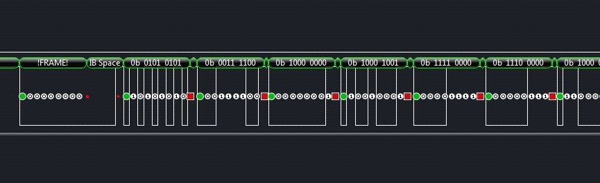
А вот пример из кода:
Сначала нужно считать данные состояния, это обязательное условие из даташита:
void GetFullStatus (void)
<
// PREPARING FRAME
SyncLIN (); // Sync Break и Sync Field
DataTX(0b00111100); // Identifier
DataTX(0x80); // AppCMD
DataTX(0x81); // CMD
DataTX(0b11110000); // slave address
DataTX(0xff); // DATA
DataTX(0xff); // DATA
DataTX(0xff); // DATA
DataTX(0xff); // DATA
DataTX(0xff); // DATA
DataTX(0b00001101); // CHK байт контроля ошибок
// READING FRAME
SyncLIN (); // Sync Break и Sync Field
DataTX(0B01111101);
В ответ драйвер мотора посылает восемь байт своего состояния, после этого можно слать команду установки на нужную позицию — мотор оживает и делает нужное количество шагов:
SyncLIN ();// Sync Break и Sync Field
DataTX(0x3c); // Identifier
DataTX(0x80); // AppCMD
DataTX(0x8b); // CMD
DataTX(0xf0); // AD1[6:0] slave address 1 шагового мотора
DataTX(0x55); // DATA нужная позиция 1 мотора (16 бит, поэтому в два захода)
DataTX(0xff); // DATA нужная позиция 1 мотора
DataTX(0xNN); // DATA slave address 2-го шагового мотора
DataTX(0xNN); // DATA нужная позиция 2 мотора (16 бит, поэтому в два захода)
DataTX(0xNN); // DATA нужная позиция 2 мотора
DataTX(0xNN); // CHK контрольная сумма
Это минимальный код, заставляющий двигаться шаговый мотор. В железе это вышло так:
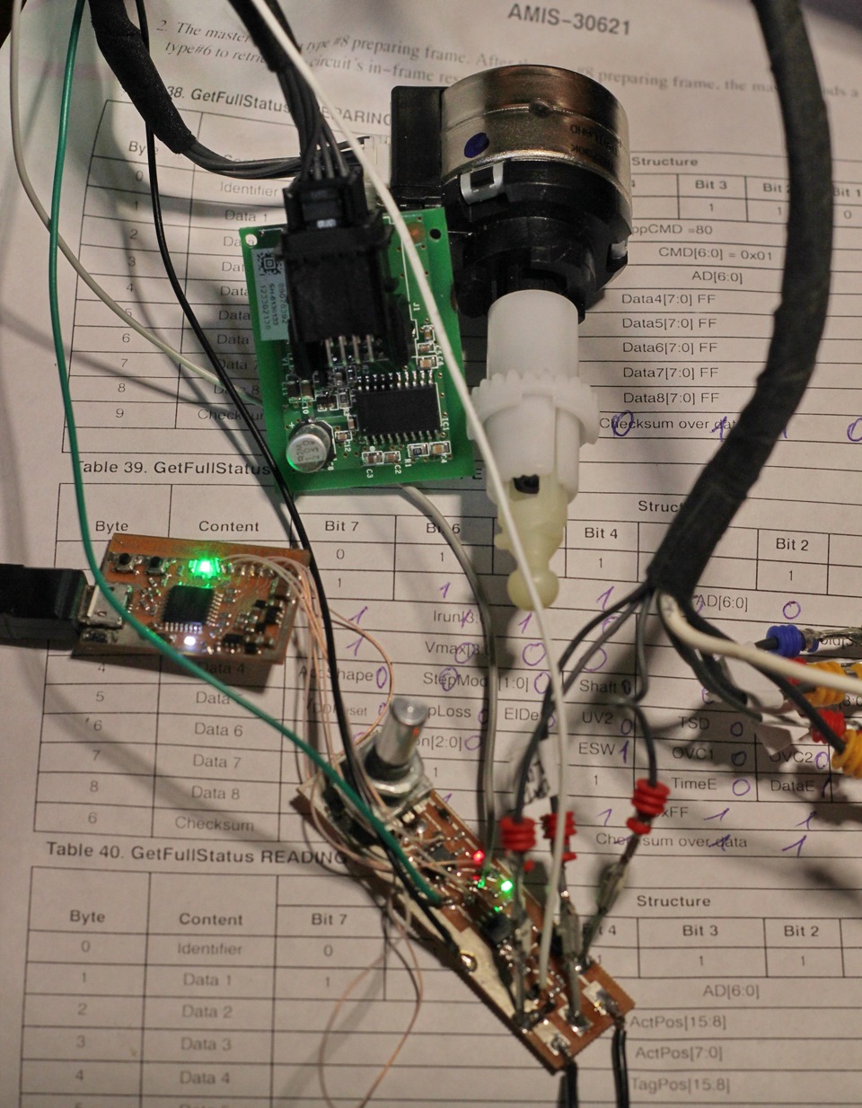
Внизу: плата контроллера
Слева: программатор
Вверху: шаговый мотор и драйвер
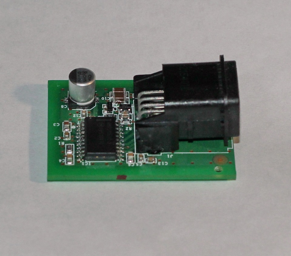
Плата драйвера крупнее:
В итоге можно организовать корректор вертикального положения фар, управляемый при помощи энкодера (управлять шаговым мотором при помощи шагового энкодера — что может быть лучше?) с отдельным управлением левой и правой фарой (для сервисной настройки фар) с возможностью оперативного изменения угла энкодером и все это от одного управляющего проводка.
LIN Bus Explained — A Simple Intro [2023]
In this guide we introduce the Local Interconnect Network (LIN) protocol basics incl. LIN vs. CAN, use cases, how LIN works and the six LIN frame types.
Note: This is a practical intro so we will also look at the basics of LIN bus data logging.
Learn more below!
You can also watch our LIN bus intro video above — or get the PDF.
In this article
(updated April 2022)

What is LIN bus?
LIN bus is a supplement to CAN bus.
It offers lower performance and reliability — but also drastically lower costs. Below we provide a quick overview of LIN bus and a comparison of LIN bus vs. CAN bus.
- Low cost option (if speed/fault tolerance are not critical)
- Often used in vehicles for windows, wipers, air condition etc..
- LIN clusters consist of 1 master and up to 16 slave nodes
- Single wire (+ground) with 1-20 kbit/s at max 40 m bus length
- Time triggered scheduling with guaranteed latency time
- Variable data length (2, 4, 8 bytes)
- LIN supports error detection, checksums & configuration
- Operating voltage of 12V
- Physical layer based on ISO 9141 (K-line)
- Sleep mode & wakeup support
- Most newer vehicles have 10+ LIN nodes
LIN bus vs CAN bus
- LIN is lower cost (less harness, no license fee, cheap nodes)
- CAN uses twisted shielded dual wires 5V vs LIN single wire 12V
- A LIN master typically serves as gateway to the CAN bus
- LIN is deterministic, not event driven (i.e. no bus arbitration)
- LIN clusters have a single master — CAN can have multiple
- CAN uses 11 or 29 bit identifiers vs 6 bit identifiers in LIN
- CAN offers up to 1 Mbit/s vs. LIN at max 20 kbit/s
LIN bus history
Below we briefly recap the history of the LIN protocol:
- 1999: LIN 1.0 released by the LIN Consortium (BMW, VW, Audi, Volvo, Mercedes-Benz, Volcano Automotive & Motorola)
- 2000: The LIN protocol was updated (LIN 1.1, LIN 1.2)
- 2002: LIN 1.3 released, mainly changing the physical layer
- 2003: LIN 2.0 released, adding major changes (widely used)
- 2006:LIN 2.1 specification released
- 2010:LIN 2.2A released, now widely implemented versions
- 2010-12:SAE standardized LIN as SAE J2602, based on LIN 2.0
- 2016: CAN in Automation standardized LIN (ISO 17987:2016)

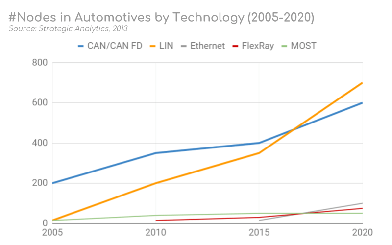
LIN bus future
The LIN protocol serves an increasingly important role in providing low cost feature expansion in modern vehicles.
As such, LIN bus has exploded in popularity in the last decade with >700 million nodes expected in automotives by 2020 vs
200 million in 2010.
Cybersecurity & new protocols
However, with the rise of LIN also comes increased scrutiny in regards to cyber security. LIN faces similar risk exposures as CAN — and since LIN plays a role in e.g. the seats and steering wheel, a resolution to these risks may be necessary.
The future automotive vehicle networks are seeing a rise in CAN FD, FlexRay and automotive Ethernet. While there’s uncertainty regarding the role each of these systems will play in future automotives, it’s expected that LIN bus clusters will remain vital as the low cost solution for an ever increasing demand for features in modern vehicles.
As part of designing a more inclusive wording for LIN bus, the CiA/ISO/SAE agreed wording will transition to commander/responder. As such, this will be the de facto standard wording used in most guidelines and LIN bus specifications going forward.
LIN bus applications
Today, LIN bus is a de facto standard in practically all modern vehicles — with examples of automotive use cases below:
- Steering wheel: Cruise control, wiper, climate control, radio
- Comfort: Sensors for temperature, sun roof, light, humidity
- Powertrain: Sensors for position, speed, pressure
- Engine: Small motors, cooling fan motors
- Air condition: Motors, control panel (AC is often complex)
- Door: Side mirrors, windows, seat control, locks
- Seats: Position motors, pressure sensors
- Other: Window wipers, rain sensors, headlights, airflow
Further, LIN bus is also being used in other industries:
- Home appliances: Washing machines, refrigerators, stoves
- Automation: Manufacturing equipment, metal working
Example: LIN vs CAN window control
LIN nodes are typically bundled in clusters, each with a master that interfaces with the backbone CAN bus.
Example: In a car’s right seat you can roll down the left seat window. To do so, you press a button to send a message via one LIN cluster to another LIN cluster via the CAN bus. This triggers the second LIN cluster to roll down the left seat window.
How does LIN bus work?
LIN communication at its core is relatively simple:
A master node loops through each of the slave nodes, sending a request for information — and each slave responds with data when polled. The data bytes contain LIN bus signals (in raw form).
However, with each specification update, new features have been added to the LIN specification — making it more complex.
Below we cover the basics: The LIN frame & six frame types.
The LIN frame format
In simple terms, the LIN bus message frame consists of a header and a response.
Typically, the LIN master transmits a header to the LIN bus. This triggers a slave, which sends up to 8 data bytes in response.
This overall LIN frame format can be illustrated as below:
LIN frame fields
Break: The Sync Break Field (SBF) aka Break is minimum 13 + 1 bits long (and in practice most often 18 + 2 bits). The Break field acts as a “start of frame» notice to all LIN nodes on the bus.
Sync: The 8 bit Sync field has a predefined value of 0x55 (in binary, 01010101). This structure allows the LIN nodes to determine the time between rising/falling edges and thus the baud rate used by the master node. This lets each of them stay in sync.
Identifier: The Identifier is 6 bits, followed by 2 parity bits. The ID acts as an identifier for each LIN message sent and which nodes react to the header. Slaves determine the validity of the ID field (based on the parity bits) and act via below:
- Ignore the subsequent data transmission
- Listen to the data transmitted from another node
- Publish data in response to the header
Typically, one slave is polled for information at a time — meaning zero collision risk (and hence no need for arbitration).
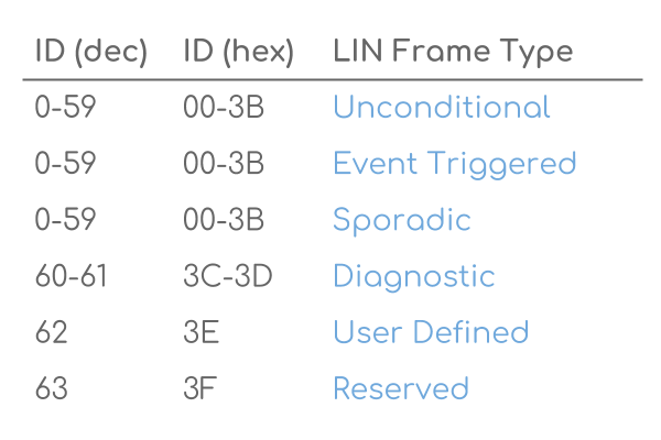
Note that the 6 bits allow for 64 IDs, of which ID 60-61 are used for diagnostics (more below) and 62-63 are reserved.
Data: When a LIN slave is polled by the master, it can respond by transmitting 2, 4 or 8 bytes of data. The data length can be customized, but it is typically linked to the ID range (ID 0-31: 2 bytes, 32-47: 4 bytes, 48-63: 8 bytes). The data bytes contain the actual information being communicated in the form of LIN signals. The LIN signals are packed within the data bytes and may be e.g. just 1 bit long or multiple bytes.
Checksum: As in CAN, a checksum field ensures the validity of the LIN frame. The classic 8 bit checksum is based on summing the data bytes only (LIN 1.3), while the enhanced checksum algorithm also includes the identifier field (LIN 2.0).
Since the low cost LIN slaves are often low performing, delays may occur. To mitigate this, inter byte space can optionally be added as illustrated below. Further, between the header and response, there is a ‘response space’ that allows slave nodes sufficient time to react to the master’s header.
Logging LIN bus data
The CANedge lets you easily log LIN bus data to an 8-32 GB SD card. Simply connect it to your LIN application to start logging — and process the data via free software/APIs.
For example, the free asammdf GUI/API lets you DBC decode your LIN data to physical values and e.g. plot your LIN signals.
Six LIN frame types
Multiple types of LIN frames exist, though in practice the vast majority of communication is done via “unconditional frames».
Note also that each of the below follow the same basic LIN frame structure — and only differ by timing or content of the data bytes.
Below we briefly outline each LIN frame type:
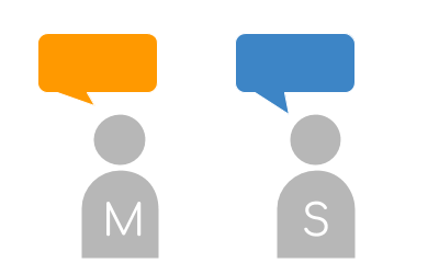 Unconditional Frames
The default form of communication where the master sends a header, requesting information from a specific slave. The relevant slave reacts accordingly
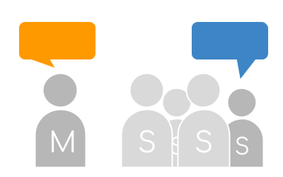 Event Trigger Frames
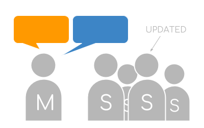
The master polls multiple slaves. A slave responds if its data has been updated, with its protected ID in the 1st data byte. If multiple respond, a collision occurs and the master defaults to unconditional frames
 Sporadic Frames
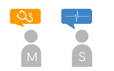
Only sent by the master if it knows a specific slave has updated data. The master «acts as a slave» and provides the response to its own header — letting it provide slave nodes with «dynamic» info
 Diagnostic Frames
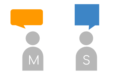
Since LIN 2.0, IDs 60-61 are used for reading diagnostics from master or slaves. Frames always contain 8 data bytes. ID 60 is used for the master request, 61 for the slave response
 User Defined Frames
ID 62 is a user-defined frame which may contain any type of information
 Reserved Frames
Reserved frames have ID 63 and must not be used in LIN 2.0 conforming LIN networks
Advanced LIN topics
Below we include two advanced topics — click to expand.
The LIN Node Configuration File (NCF) and LIN Description File (LDF)
To quickly set up LIN bus networks, off-the-shelf LIN nodes come with Node Configuration Files (NCF). The NCF details the LIN node capabilities and is a key part of the LIN topology.
An OEM will then combine these node NCFs into a cluster file, referred to as a LIN Description File (LDF). The master then sets up and manages the LIN cluster based on this LDF — e.g. the time schedule for headers.
Note that the LIN bus nodes can be re-configured by using the diagnostic frames described earlier. This type of configuration could be done during production — or e.g. everytime the network is started up. For example, this can be used to change node message IDs.
If you’re familiar with CANopen, you may see parallels to the Device Configuration File used to pre-configure CANopen nodes — and the role of Service Data Objects in updating these configurations.
A key aspect of LIN is not only saving costs, but also power.
To achieve this, each LIN slave can be forced into sleep mode by the master sending a diagnostic request (ID 60) with the first byte equal to 0. Each slave also automatically sleeps after 4 seconds of bus inactivity.
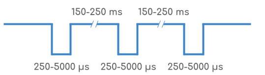
The slaves can be woken up by either the master or slave nodes sending a wake up request. This is done by forcing the bus to be dominant for 250-5000 microseconds, followed by a pause for 150-250 ms. This is repeated up to 3 times if no header is sent by the master. After this, a pause of 1.5 seconds is required before sending a 4th wake up request. Typically nodes wake up after 1-2 pulses.
LIN Description File (LDF) vs. DBC files
As part of your LIN data logger workflow, you may need to decode your raw LIN bus data to physical values. Specifically, this involves extracting LIN signals from the LIN frame payload and decoding these to human-readable form.
This process of LIN bus decoding is similar to CAN bus decoding and requires the same information:
- ID: Which LIN frame ID contains the LIN bus signal
- Name: The LIN signal name should be known
- Start bit: Start position of the LIN signal in the payload
- Length: Length of the LIN bus signal
- Endianness: LIN signals are little endian (Intel byte order)
- Scale: How to multiply the decimal value of the LIN signal bits
- Offset: By what constant should the LIN signal value be offset
- Unit/Min/Max: Additional supporting information (optional)
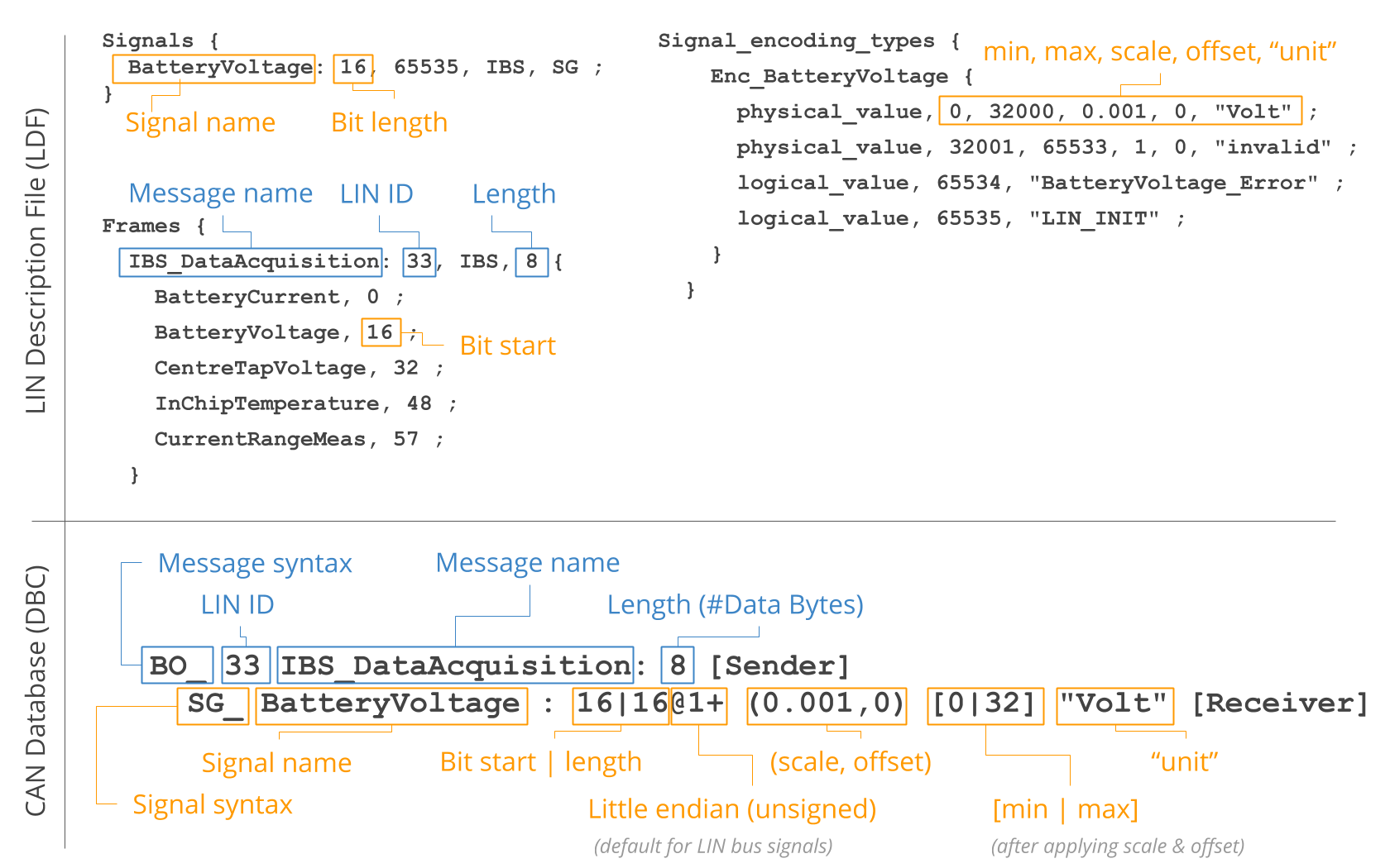
This information is typically available as part of the LIN Description File (LDF) for a local interconnect network. However, since many software tools do not natively support the LDF format, we explain below how to use DBC files as an alternative.
LIN Description File (LDF) vs. DBC files
As evident from our CAN bus intro and DBC file intro, the above entries are equivalent to the information stored in a CAN DBC file. This means that a simple method for storing LIN bus decoding rules is to use the DBC file format, which is supported by many software and API tools (incl. the CANedge software tools like asammdf). For example, you can load a LIN DBC file and your raw LIN bus data from the CANedge in asammdf to extract LIN bus signals from the data, which you can then plot, analyze or export.
In many cases, you may not have a LIN DBC file directly available, but instead you may have a LIN description file (LDF). Below we therefore focus on how you can convert the relevant LIN signal information into the DBC format.
Note: The LDF typically contains various other information relevant to the operation of the LIN bus, which we do not focus on here. For a full deep-dive on the LIN protocol and the a detailed description of the LDF specification, see the LIN protocol PDF standard.
Below we provide an example to showcase how you can extract LIN signal information from an LDF and enter it into a DBC file. We use a very simplified LIN description file (with only one signal and excluding some sections).
You can expand the below examples to see the LIN signal, BatteryVoltage, in the LDF format and in the DBC format. You can also download a raw LIN bus log file (MF4) from the CANedge2 with data for this signal, which you can open and DBC decode in asammdf:
Что такое шина LIN
Шина LIN – это простая последовательная однопроводная шина для автомобильных применений и используется в тех случаях когда применение CAN шины – дорого. По шине LIN управляются различные приводы (корректоры фар, заслонки климатической системы, приводы центрального замка), а так же собирается информация с простых датчиков (датчики дождя, света, температуры).
Для изучения шины LIN Вы можете использовать наш адаптер CAN-Hacker 3.0 с дополнительной опцией LIN анализатора.
А так же интерфейс CAN-Hacker CH-P
Пример системы управления дверью с шиной LIN и без нее:
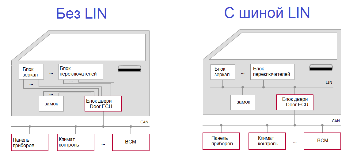
Еще пример, в автомобиле Porsche Macan 2015 г. все привода и датчики климатической системы подключены к шине LIN а сам блок климат контроля связан с автомобилем при помощи CAN шины.
Дешевизна LIN обусловлена тем что реализация протокола LIN полностью программная и строится на базе обычного UART (родственник RS232, COM порт). Так же LIN не требует применения точных времязадающих цепей – кварцевых резонаторов и генераторов. Поэтому можно применять дешевые микроконтроллеры.
Скорость передачи данных
Скорость передачи данных на шине LIN стандартная для устройств построенных на базе UART: 2400; 9600; 10400; 19200; 20000 Бод. Это немного но достаточно для передачи данных от датчиков и для управления медленными механизмами.
Электрическая реализация LIN
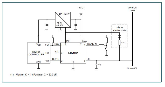
Электрически интерфейс LIN реализован так же просто. В каждом узле линия шины подтянута к шине питания +12V. Передача осуществляется опусканием уровня шины до уровня массы GND. Микроконтроллер подключается к шине LIN при помощи специальной микросхемы Трансивера, например TJA1021
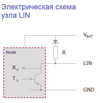
Подключение LIN трансивера к микроконтроллеру
Архитектура сети LIN
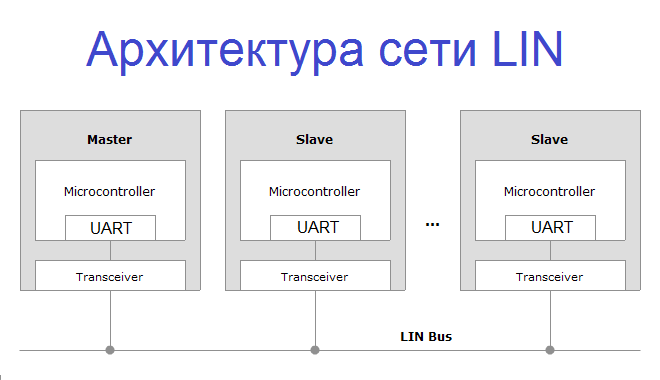
Особенностью шины LIN является то, что в сети присутствует два вида узлов: Master и Slave, Master – ведущий, Slave – подчиненный.
Master может опрашивать Slave о его состоянии, будить его, отправлять ему команды. Обмен информации на шине LIN происходит в формате обмена пакетами, и на первый взгляд может показаться что механизм идентичен шине CAN, это не так. Объясняем почему:
Структура LIN пакета выглядит так:
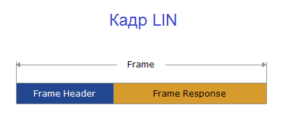
Frame – Header – заголовок кадра, который отправляется в шину Мастером. Включает в себя ID кадра
Frame – Response – данные которые отправляет Slave в ответ на запрос Master -а.
Уловите разницу – в шине CAN все узлы передают и ID кадра и данные. В шине LIN – заголовок пакета это задача Мастер-узла.
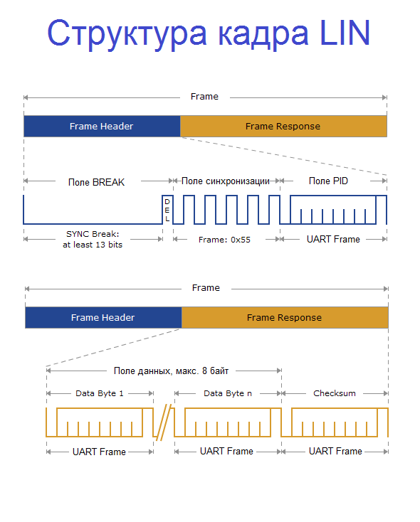
Поле Frame-Header состоит из полей:
BREAK – Это сигнал шине о том что мастер сейчас будет говорить
Поле синхронизации – это просто байт = 0x55. При его передаче приемники подстраивают свою скорость.
PID – это поле защищенного идентификатора. В дальнейшем будем писать просто – идентификатор.
Идентификатор может принимать значения от 0 до 59 (0x3B в HEX) для пользовательских пакетов. Так же возможно использование специальных служебных пакетов с ID 0x3C, 0x3D, 0x3E и 0x3F. Защищенность идентификатора заключена в следующем:

В структуре байта ID мы видим биты собственно самого идентификатора с ID0 по ID5, а затем идут два контрольных бита P0 и P1, которые рассчитываются так:
P0 = ID0 ⊕ ID1 ⊕ ID2 ⊕ ID4
P1 = ¬ (ID1 ⊕ ID3 ⊕ ID4 ⊕ ID5)
ID = 0x00 PID =0x80
ID = 0x0C PID = 0x4C
Если в PID контрольные биты рассчитаны неверно то пакет не будет обработан принимающей стороной.
В случае если мы будем эмулировать работу какого либо узла Master, предварительно изучив отправляемые им данные при помощи LIN сниффера, то нам не придется задумываться о расчете контрольных битов ID, поскольку в пакетах которые мы видим сниффером все уже посчитано до нас.
После того как Slave принял Header мастера он отвечает полем Frame Response который состоит из байтов данных в количестве от 1 до 8 и байта контрольной суммы.
Контрольная сумма (CRC) считается как инвертированная сумма всех байтов данных с переносом либо сумма всех байтов данных + значение защищенного ID . В первом случае CRC называется классической, во втором – расширенной. Вариант подсчета контрольной суммы определяется версией стандарта шины LIN. В версиях 1.xx применяется классический алгоритм, в версиях 2.xx применяется расширенный.
Обратите внимание на отсутствие поля DLC отвечающего за количество байтов данных как в CAN шине. В шине LIN количество байтов данных определяется на этапе написания ПО контроллера. Поэтому процесс обмена на шине LIN сложнее анализировать при помощи сниффера – приходится вводить специальный алгоритм разделения пакетов, который угадывает сколько байтов данных было в принятом пакете.
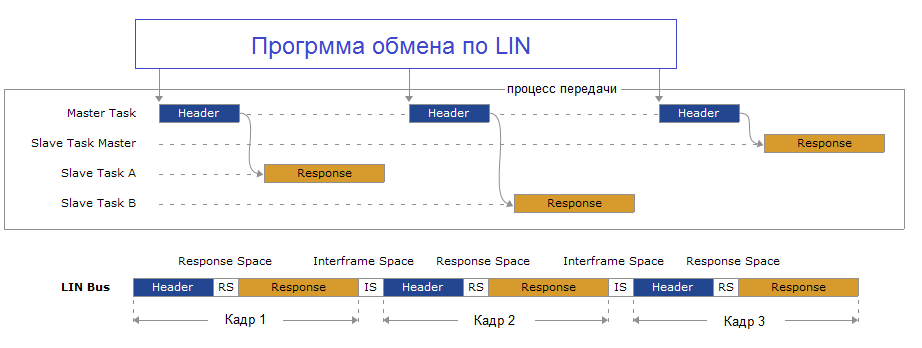
На этой схеме мы видим как один Мастер общается с двумя узлами Slave. Обратите внимание на третий кадр, в нем заголовок Header и тело пакета Response передает Мастер – это важный момент, такие кадры используются для диагностики и конфигурирования Slave узлов.
На осциллограмме обмен одного Master и одного Slave выглядит так:
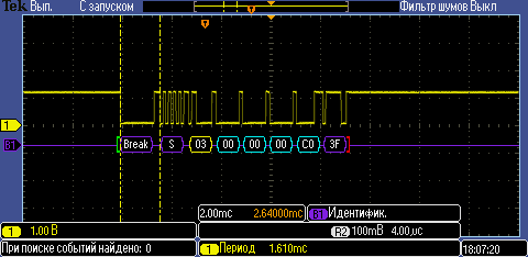
Здесь мы видим запрос мастера состоящий из полей Break – S – затем следует ответ узла Slave состоящий из четырех байт и контрольной суммы равной 0x3F.
Если мы отключим узел Slave от шины LIN, то увидим уже такую осциллограмму:
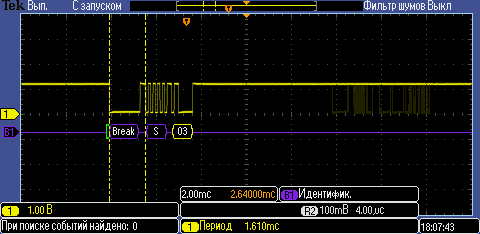
Так же в протоколе шины LIN предусмотрены и специальные служебные пакеты служащие для диагностики шины, пробуждения устройств и других функций. В этом случае Master может передавать как Frame Header так и Frame Response последовательно, тогда пакет Master -а может иметь такой вид:
ID=0x3C DATA : FF FF FF FF FF FF FF FF
Обмен диагностическими сообщениями на шине LIN выглядит так :
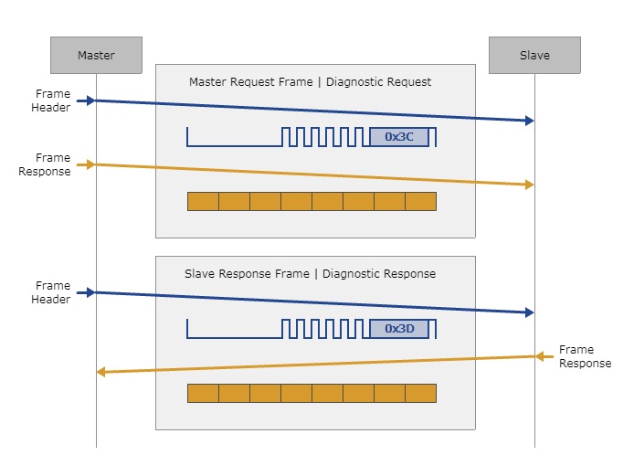
При помощи длинных пакетов Master может конфигурировать и программировать узлы Slave. Если для программирования или конфигурирования узла LIN необходимо более 8 байт, то поток данных сегментируется и пересылается частями. Механика передачи данных определяется специальным транспортным протоколом работающим поверх физики шины LIN, о нем мы напишем в следующих статьях.
Видео пример работы с шиной LIN и адаптером CAN-Hacker 3.2